Under construction.
There is a complex algorithm executed in the MatchingCube.
It takes the current impedance as input to calculate the next step for CL and CT.
This calculation can be - and in some cases it must be - influenced.
This application note describes how to do this.
Prepare the system.
Mount the MatchingCube into your plasma system and connect it accordingly.
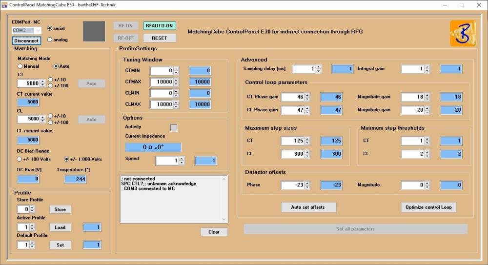
Control the device with the ControlPanel.
Set Matching Mode to Manual.
Set CL and CT to values that will allow ignition.
Turn the RF generator on with the minimum power necessary for igniting plasma.
Match the load manually until Current impedance shows close to 50Ω ∠0°.

Collect data for CL.
| | | | | matched | | | |
| CL | | | | | ———— | ———— | ———— |
| MAG | ———— | ———— | ———— | 50Ω | | | |
| PHASE | | | | 0° | | | |
| PREF | | | | 0W | | | |
Collect data for CT.
| | | | | matched | | | |
| CT | | | | | ———— | ———— | ———— |
| MAG | ———— | ———— | ———— | 50Ω | | | |
| PHASE | | | | 0° | | | |
| PREF | | | | 0W | | | |
Determine control loop parameters.
CL: Magnitude Gain
CL: Phase Gain
CT: Magnitude Gain
CT: Phase Gain
For calculating the gain parameters more accurately
request a specific calculation sheet from us or
send your findings to us, we will do the math for you
Test AutoMatch.
The MatchingCube shall now hold the matching condition.
Optimize control loop parameters.
To be continued.
© barthel HF-Technik GmbH 2024 – T +49 (0)241 45015-40 – Imprint & Privacy

